Acceptability Criteria for Submissions Related to Orders MO-001-2016 and MO-003-2018
Acceptability Criteria for Submissions Related to Orders MO-001-2016 and MO-003-2018 [PDF 954 KB]
Table of Contents
- 1. Purpose
- 2. Mitigation Measures
- 3. Basic Requirements
- 4. Estimation of a Representative Specified Minimum Yield Strength
- 5. Short-term Remediation
- 6. Engineering Assessment Demonstrating Long-Term Fitness for Service
- Appendix A – Relevant CSA Requirements
- Appendix B – Acceptability Criteria for MO-001-2016 and MO-003-2018 Flow Chart
1. Purpose
After identifying material quality concerns, the National Energy Board (NEB) issued Order MO-001-2016 which required companies to conduct and file an Engineering Assessment (EA) if they had installed components from specific manufacturers over a defined time period. The purpose of the EA is to demonstrate the fitness for service of pipe or components identified as having mechanical properties that potentially did not meet standard or company specifications. To provide consistency in its review of the EAs the NEB developed EA Acceptability Criteria to evaluate the filings made in response to the order.Footnote 1
To address subsequently identified quality concerns, the NEB has followed up by issuing Order MO-003-2018 which is not limited to specific manufacturers or time of manufacture. In the event that a company identifies that it has components or pipe with mechanical properties that do not meet standards or company specifications then, where applicable, they are required to conduct an EA that demonstrates the fitness for service of the pipe or components. The Board may request the EA be submitted for review, or may review the EA during a compliance verification activity.Footnote 2
The Board is issuing these Acceptability Criteria to highlight the Board’s expectations and to aid companies, when they are conducting their EAs, to determine the fitness for service assessment of pipe or components. The use of these Acceptability Criteria will provide a consistent and transparent approach to the evaluation of the EAs by companies and the Board.
If you have any questions regarding the Orders or Acceptability Criteria please contact Pipeline Integrity personnel at the Board through our toll free number at 1-800-899-1265.
2. Mitigation Measures
These criteria may be applied to two following mitigation strategies:
- Resolution of the Issue (e.g. removal or appropriate reinforcement), or
- Short Term Fitness for Service (e.g. lower operating pressure)
3. Basic Requirements
NEB Safety Advisory (SA) 2016-01 (Potential for Substandard Properties of Pipeline Fitting Materials) and Order MO-001-2016 (Identification of Pipe and Fittings with the Potential to Exhibit Substandard Material Properties) both highlight that the current published codes and standards including but not limited to those published by the Canadian Standards Association (Standards) appear to be insufficient to prevent the manufacture of pipe and fittings with substandard material properties. Therefore, a CompanyFootnote 3 must demonstrate that it is not relying solely on the Certificate of Compliance and the associated Material Test Reports (MTR) to verify that the material properties meet the minimum requirements.
3.1 Manufacturing Stage
Demonstrated evidence of purchaser and manufacturer quality assurance (QA) and quality control (QC)
- Company or its contractor conducting onsite qualification/verification of manufacturing facility and processes.
- Documentation and supporting tests verifying compliance with the applicable version of the standard used:
- Canadian Standards Association (CSA) Z245.11, Clause 15 – a Certificate of Compliance and, when required in the purchase order, the results of any mechanical tests specified by the purchaser; or
- MSS SP-75 Clause 16 – a Certified Material Test Report (CMTR)
- Company must be able to demonstrate that the minimum wall thickness (particularly at the intrados of bends) is verified for a representative sample of fittings from each lot.
- Company, Engineering Procurement and Construction (EPC) or Distributor specifications exceed the applicable version of the CSA 245.11 or Manufacturers Standardization Society (MSS) SP-75 standards. The exceedance must be able to demonstrate:
- adequate manufacturing quality assurance (e.g. additional mechanical (destructive) tests or experimental stress analysis at the highest stressed location in the fitting); and
- an appreciable level of safety added to the fitting design (e.g. additional wall thickness).
- Third party (QA/QC) oversight at the manufacturing plant during the manufacture of a representative sample of the actual fittings being purchased. Scope of third party oversight to be provided in the fillings.
- Mechanical tests conducted on specimens taken from an actual fitting (not from a test coupon) that are intended to represent the fitting.
3.2 Installation and Operating Stage
Demonstrated evidence to support the following:
- The hoop stress due to maximum operating pressure (MOP) is less than or equal to 56% of the SMYSFootnote 4 in the adjacent pipe; or
- The level of hydrostatic strength test pressure for the fitting is a minimum of 15%Footnote 5greater than the test pressures prescribed in table 8.1 of CSA Z662-15, or the strength test pressure for the fitting is 100% specified minimum yield strength (SMYS)Footnote 6.
In addition:
- No leaks or ruptures occurred on any pipe or fitting during the hydrostatic pressure tests;
- No evidence of yielding after a strength hydro test of the pipe or fitting; this may be demonstrated by either direct measurements or, if applicable, inferred by examination(e.g. coating condition, ovality, or expansion); and
- No leaks or ruptures have occurred in fittings or pipe since in service.
4. Estimation of a Representative Specified Minimum Yield Strength
Company must be able to estimate a representative SMYS for the fittings of concern, for example:
- Yield stress determined from tensile test on fitting (representative samples);
- The use of ASTM A370 or a similar technology to convert hardness values to yield might be considered with ratio ≤ 0.70 – if the Company can demonstrate a correlation between hardness and tensile stress.
The Company must be able to demonstrate that the estimated SMYS of the fittings is conservative and repeatable. The probability of the estimated SMYS being exceeded by the actual yield stress of the fitting must be demonstrated to be acceptably high (e.g. comparable to that for the line pipe steel).
The estimated SMYS must be used in the Integrity Management Plan (IMP) for long-term fitness for service assessments.
5. Short-term Remediation
The short-term remediation is considered acceptable if the Company is able to demonstrate that the fitting(s) can be safely operated at the MOP taking into account all loads.
6. Engineering Assessment Demonstrating Long-Term Fitness for Service
- An engineering assessment has been conducted in accordance with CSA Z662-15 to demonstrate long-term fitness for service (FFS). This comprehensive EA must evaluate all potential hazards expected over the life of the pipeline and the associated consequences in the event of a leak or rupture. The consequence analysis must examine in detail the public safety risk and environmental risk.
- A plan and commitment to conduct continuous monitoring as per the company’s integrity management program requirements.
- A plan to mitigate by either replacement of pipe or fittings or suitable reinforcement.
Appendix A – Relevant CSA Requirements
For guidance and reference the following, below are the CSA Z662-15 EA requirements for materials (Clause 5) and operating pipelines (Clause 10):
**************
5.8 Engineering assessments
Engineering assessments for material qualification or acceptance shall be conducted and documented in accordance with the requirements of Clause 3.3, and the analysis shall include consideration of the following, as applicable:
- a) the design basis, including
- i) service fluid;
- ii) operating pressure and temperature range; and
- iii) the general and site-specific loading conditions that are anticipated throughout the design life of the material;
- b) material specifications and properties;
- c) intended range of operating conditions;
- d) loads and dynamic effects as specified in Clause 4.2.4;
- e) manufacturing process and installation method;
- f) technical data and test records
- g) time and/or cycle dependant material degradation;
- h) environmental conditions and potential environmental consequences;
- i) hazard type, frequency, and magnitude, including any hazards associated with the presence of foreign structures or environmental conditions; and
- j) consequences of failure.
10.1.1
Engineering assessments of existing pipeline systems shall be conducted and documented in accordance with the requirements of Clause 3.3 and the analysis shall include consideration of the following, as applicable:
- a) design basis of the pipeline system, including service fluid, operating pressure and temperature range, and the general and site-specific loading and operating conditions that are anticipated throughout its design life;
- b) material specifications and properties;
- c) manufacturing process and installation method;
- d) construction and testing specifications;
- e) the physical configuration and constraints of the part of the pipeline system that are the subject of the engineering assessment;
- f) condition of the piping, including types of imperfections, dimensions, and dimensional uncertainty;
- g) mechanism or mode of imperfection formation, growth, and failure;
- h) service, operating and maintenance history;
- i) appropriateness of repair methods;
- j) interaction of identified hazards; and
- k) risk assessment.
Notes:
1) Reference should be made to the records required in Clauses 5.7, 6.1.5, 7.6.3, 7.14.9, 7.15.11, 8.8.7, 9.9.4, 9.9.5, 10.4, and 16.5.2.
2) Risk assessment (see Annex B), pipeline system integrity management programs (see Annex N), and reliability based design and assessment (RBDA) (see Annex O) can provide valuable information and guidance for the engineering assessment.
10.1.2
Where the information required in Clause 10.1.1 is not available, the operating company shall conduct inspections or testing, or make conservative assumptions that can be supported by rational analysis and valid system experience, to enable the engineering assessment to be carried out.
Notes:
1) Examples of inspection and testing include in-line inspection (see Annex D), pressure testing (see Clause 10.3.9.), test excavations to verify coating type and condition and effectiveness of cathodic protection, and testing pipe samples for mechanical properties.
2) NACE SP0502 for external corrosion, NACE SP0204 for stress corrosion cracking, NACE SP0206 for internal corrosion of normally dry gas pipelines, NACE SP0110 for internal corrosion of wet gas pipelines, and NACE SP0208 for internal corrosion of liquid petroleum pipelines provide guidance for determining piping condition using a methodology such as direct assessment.
Appendix B – Acceptability Criteria for MO-001-2016 and MO-003-2018 Flow Chart
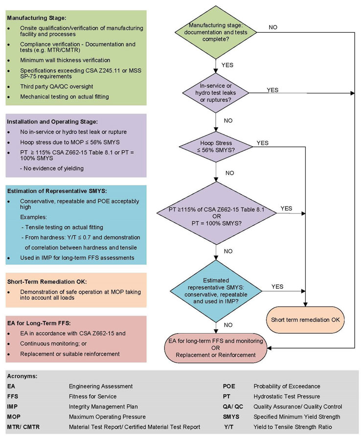
Graphic Description
Acceptability criteria flow chart for submissions pursuant to MO-001-2016 and MO-003-2018. The flowchart provides a visual summary of the content of this document.
- Date modified: